Our Attitude – Always at your service
Special technical subjects
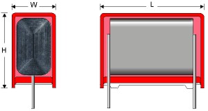
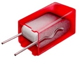
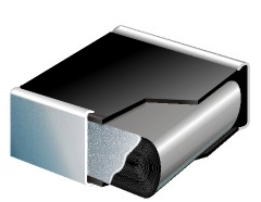
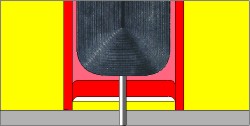
WIMA box encapsulation
Both, SMD and through-hole WIMA DC capacitors are produced with the proven box technology, showing the following substantial advantages in comparison with non-encapsulated, moulded or dipped capacitor versions:
- Safe protection of the capacitor element against the mechanical stresses which occur during processing and operation.
- No danger of delamination, internal cracks or tearing away of the contacts due to similar expansion coefficient and the elasticity of the construction.
- Excellent self-healing properties of metallized WIMA capacitors due to pressure free layers in the winding element.
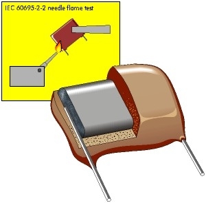
- Flame retardant plastic case in accordance with UL 94 V-0.
- Clearly defined dimensions allows for close placement and exact setting of parts on PC-boards. Even larger parts are easily robotically insertable.
- Easy second source because of standardized box size.
WIMA self-healing behaviour as a quality standard
The capacitors manufactured by WIMA in winding technology are produced as single winding capacitors. The most effective pressure on the layers necessary for good self-healing behaviour can be individually adjusted for each capacitor.
WIMA capacitors are known for their excellent self-healing behaviour. A DC voltage test is used to demonstrate the self-healing properties:
This clearly shows that stacked MKT film capacitors short-circuit after a few self-healing processes. Also, the rate of the breakdown voltage is usually distinctly lower. A low loading capacity and a reduced life time are the result. WIMA capacitors, on the other hand, are surprisingly hardy. As well as having very high breakdown voltage, they self-heal much more frequently than corresponding stacked film capacitors. The test clearly proves the high reliability and long life-span of WIMA MKS capacitors, well above the data given in the catalogue.
- the capacitor to be tested is connected over a series resistance of R ~ 10 k at with adjustable direct voltage source.
- the voltage on the capacitor is observed with a line recorder or an oscilloscope (see diagram).
- the voltage applied to the capacitor is continually increased, over and above the rated voltage for the capacitor, up to the first self-healing process. The line recorder shows clear breakdowns in the capacitor voltage and then recharging until the next self-healing occurs.
This clearly shows that stacked MKT film capacitors short-circuit after a few self-healing processes. Also, the rate of the breakdown voltage is usually distinctly lower. A low loading capacity and a reduced life time are the result. WIMA capacitors, on the other hand, are surprisingly hardy. As well as having very high breakdown voltage, they self-heal much more frequently than corresponding stacked film capacitors. The test clearly proves the high reliability and long life-span of WIMA MKS capacitors, well above the data given in the catalogue.
Selection of capacitors for pulse applications
The maximum permissible AC voltage that can be applied to capacitors in sinusoidal waveform applications, can be determined from the graphs in the respective capacitor ranges.
However, where pulse conditions exists, the following procedure is to be observed to ensure that the correct capacitor rating is selected for a particular duty:
Rated voltage Ur: The rated voltage of a capacitor against a zero potential reference point shall take into consideration that the dielectric strenght of the capacitor film diminishes with rising frequency. The calculation of the required rated voltage of a capacitor must therefore allow for the correction factor k; where k = dielectric strength of the film at the frequency f in % is shown in graph 1.
Graph 1: Dielectric strength of Polypropylene film as a factor of frequency (general guide).
The calculation of the required dielectric strength is shown in the following example(Umin, Umax have the same polarity).
Furthermore the rms voltage derived from the peak to peak voltage shall not be greater than the nominal AC voltage rating of the capacitor to avoid the ionization inception level:
Urms < UACrated
Maximum current: The voltage gradient or rise time of the pulse is taken as the reference point when calculating the maximum current rating of the end contacts. The maximum possible current load on the end contacts is calculated by means of the voltage rise of the pulse (pulse rise time F).
Imax = F x C x 1.6
The data of the rated pulse rise time Fr for pulses equal to the rated rated voltage figure in the technical data of the different types. With low voltage rise in operation (UPP) the permissible current load is calculated as follows:
for example Ur = 63 V, UPP = 12 V, Fr = 50 V/µsec.
hence Fmax
When using maximum current ratings, self-heating must be taken into account at higher frequencies, and must not exceed 8 K.
Dissipation (heat losses): The heat dissipated by a capacitor when stressed by non-sinusoidal voltages or when under pulse conditions can be approximately determined from the following formula:
pulse frequency =
temperature rise in K =
Table 1: The data is for ordinary assembly and ventilation conditions avoiding radiant heat within the chassis of the equipment.
In applications where reliability is critical, it is recommended to measure the surface temperature of the capacitor and to take into account that the temperature within that capacitor will be approximately 5 K above the case temperature.
Determining the permissible AC voltage and AC current at given frequencies.
To determine the permissible AC voltage (sinusoidal) for applications in a higher frequency spectrum, graphs showing AC voltage derating with frequency are available for the respective WIMA series. The diagrams refer to a permissible self-heating of:
Δϑ < 10 K.
For the WIMA MKP 10 / 0.01µF / 630VDC/400VAC, for example, this shows - when f = 50kHz - a permissible AC voltage of
Urms = 280 V (graph 2).
Graph 2: Permissible AC voltage in relation to frequency at 10°C internal temperature rise (general guide).
The AC voltage given in the diagrams can also be used to determine the maximum effective current
The calculated maximum value of the effective current
must not exceed the maximum current rating specified in the maximum pulse rise time calculation (see Fmax above). In this case, the operating AC voltage is to be reduced accordingly.
However, where pulse conditions exists, the following procedure is to be observed to ensure that the correct capacitor rating is selected for a particular duty:
Rated voltage Ur: The rated voltage of a capacitor against a zero potential reference point shall take into consideration that the dielectric strenght of the capacitor film diminishes with rising frequency. The calculation of the required rated voltage of a capacitor must therefore allow for the correction factor k; where k = dielectric strength of the film at the frequency f in % is shown in graph 1.
Graph 1: Dielectric strength of Polypropylene film as a factor of frequency (general guide).
The calculation of the required dielectric strength is shown in the following example(Umin, Umax have the same polarity).
Furthermore the rms voltage derived from the peak to peak voltage shall not be greater than the nominal AC voltage rating of the capacitor to avoid the ionization inception level:
Urms < UACrated
Maximum current: The voltage gradient or rise time of the pulse is taken as the reference point when calculating the maximum current rating of the end contacts. The maximum possible current load on the end contacts is calculated by means of the voltage rise of the pulse (pulse rise time F).
Imax = F x C x 1.6
The data of the rated pulse rise time Fr for pulses equal to the rated rated voltage figure in the technical data of the different types. With low voltage rise in operation (UPP) the permissible current load is calculated as follows:
| Fmax = UrUPP x Fr |
for example Ur = 63 V, UPP = 12 V, Fr = 50 V/µsec.
hence Fmax
6312
x 50 = 262.5 V/µsec.When using maximum current ratings, self-heating must be taken into account at higher frequencies, and must not exceed 8 K.
Dissipation (heat losses): The heat dissipated by a capacitor when stressed by non-sinusoidal voltages or when under pulse conditions can be approximately determined from the following formula:
| PV | = Urms 2 x ωC x tanδ |
| PV | = dissipation in Watts (see table 1 for the max. W per K). |
| Urms | = root mean square value of the AC voltage share |
| ω | = 2π x f, where f is the repetition frequency of the pulse waveform. |
| C | = capacitance in Farad |
| tanδ | = dissipation factor corresponding to the frequency of the steepest part of the pulse. |
pulse frequency =
1pulse width
temperature rise in K =
calculated dissipationspecific dissipation
(see table 1)| Printed circuit module PCM (in mm) |
Specific dissipation in Watts per K above the ambient temperature |
| 2.5 5 7.5 10 15 22.5 27.5 37.5 |
0.0025 0.004 0.006 0.0075 0.012 0.015 0.025 0.03 |
Table 1: The data is for ordinary assembly and ventilation conditions avoiding radiant heat within the chassis of the equipment.
In applications where reliability is critical, it is recommended to measure the surface temperature of the capacitor and to take into account that the temperature within that capacitor will be approximately 5 K above the case temperature.
Determining the permissible AC voltage and AC current at given frequencies.
To determine the permissible AC voltage (sinusoidal) for applications in a higher frequency spectrum, graphs showing AC voltage derating with frequency are available for the respective WIMA series. The diagrams refer to a permissible self-heating of:
Δϑ < 10 K.
For the WIMA MKP 10 / 0.01µF / 630VDC/400VAC, for example, this shows - when f = 50kHz - a permissible AC voltage of
Urms = 280 V (graph 2).
Graph 2: Permissible AC voltage in relation to frequency at 10°C internal temperature rise (general guide).
The AC voltage given in the diagrams can also be used to determine the maximum effective current
| XC = 1ω x C = 12π x 50kHz x 0.01 µF |
XC = 318 Ω |
| IC = UCXC = 280 V~318 MΩ |
IC = 0.88 A |
The calculated maximum value of the effective current
| IP = IC x √2 = 0.88 A x √2 | IP = 1.24 A |
Selection example for pulse application capacitors
Determination of the nominal voltage
Calculation is based on an operating temperature < +60°C unless other data is given by the user.
Ur > 350 V
Urms 85 V (referring to AC voltage share)
Selected nominal voltage: 400VDC / 250VAC pin spacing 27.5mm
Permissible voltage gradient
The voltage rise time is
350 V4 µsec
~ 87.5 V/µsec.Value from the table "pulse rise time WIMA FKP 1": 7000 V/µsec.
The calculated voltage gradient is lower than the permissible value shown in the catalogue for this capacitor.
Dissipation
Given:
Urms = 85 V
f = 32 kHz
C = 0.1 µF
The frequency determined from the steepest part of the pulse is:
Pulse width = 15 µsec = 1 cycle.
Hence pulse frequency =
115 x 10-6
~ 66 kHzThe tanδ of WIMA FKP 1 at 66 kHz ~ 10 x 10-4 (Polypropylene graph: Dissipation factor change versus frequency)
Pd = 852 x 2π x 32 x 103 x 0.1 x 10-6 x 10 x 10-4 ~ 0.145 Watts.
The selected capacitor has a pin spacing of 27.5mm
(Selection of capacitors for pulse applications: Table 1, specific dissipation = 0.025 Watts/K) and the temperature rise due to self-heating is:
Temperature rise =
0.145 Watts0.025 Watts/K
~ + 6K.The temperature rise plus the max. ambient temperature = max. permissible operating temperature (taking into account the voltage derating in the (Electrical Data WIMA FKP 1). If the permissible temperature is exceeded, then select a capacitor with a higher voltage rating.
Alternatively, our engineers will submit their recommendations upon receipt of voltage and current oscillogrammes. Questionnaire available on demand at WIMA Sales Office by phone +49 621 86295-0 or e-mail sales@wima.de.
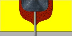
Self-Inductance Depends on Construction Principle
Depending on the construction, an alternating current in the capacitor winding creates a more or less distinctive magnetic field which can be measured as inductance messen lässt.
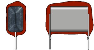
The tape length of the winding element determines the value of the self-inductance
Modern plastic film capacitors are contacted over the whole end surface of the winding element. In this way the self-inductance of the winding element is short-circuited. The self-inductance is reduced to the PCM (0.8 nH/mm) and the remaining length of the terminating wires (in case of SMD capacitors the distance between the soldering plates).
Average value for practical applications: inductance related to length = 0.8 nH/mm
Example: length of the terminating wires = 2 x 3 mm + PCM
Old Type with High Self-Inductance
The tape length of the winding element determines the value of the self-inductance
Modern WIMA Type
Modern plastic film capacitors are contacted over the whole end surface of the winding element. In this way the self-inductance of the winding element is short-circuited. The self-inductance is reduced to the PCM (0.8 nH/mm) and the remaining length of the terminating wires (in case of SMD capacitors the distance between the soldering plates).
Average value for practical applications: inductance related to length = 0.8 nH/mm
Example: length of the terminating wires = 2 x 3 mm + PCM
WIMA MKS 02 / PCM 2.5 mm
Self-inductance L < 8 nH
WIMA SMD /Size Code 1812
Self-inductance L < 6 nH
Increasing winding lengths in relation to the capacitance result in a large bonding area and guarantee low ESR values.
Thus plastic film capacitors stand out because of their HF properties which are the same as or better than those of ceramic capacitors of comparable size.
Circuit arrangements of capacitors
In parallel
| Ctotal = C1 + C2 + ... |
![]()
In series
1Ctotal = 1C1 +1C2 + ... |
![]()
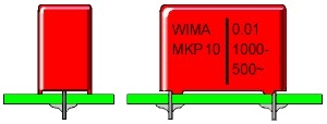
Marking of WIMA capacitors
SMD capacitors
Marking of WIMA SMD capacitors was gradually ceased as of July 2003. Identification is possible by the labelling of packages and delivery notes respectively.
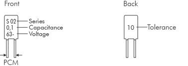
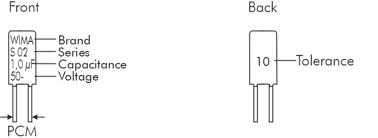
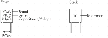
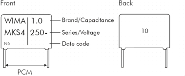
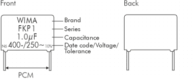
Through-Hole Capacitors
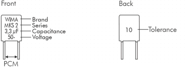
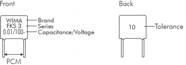
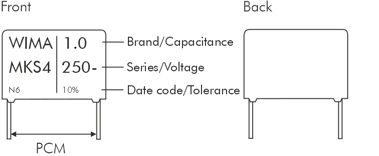
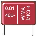
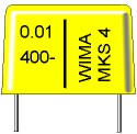
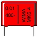
In general, WIMA through-hole capacitors are marked on the front side of the box in plain text with brand name, capacitor series, capacitance, nominal voltage, date code and tolerance. Capacitors with PCM smaller than 15 mm will have the tolerance indicated on the reverse. Standard tolerance 20% is not marked.
PCM 2.5 mm box size < 3.8 x 8.5 x 4.6 mm
PCM 2.5 mm box size > 3.8 x 8.5 x 4.6 mm
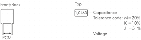
PCM 5 mm box size < 8.5 x 10 x 7.2 mm
PCM 5 mm box size > 8.5 x 10 x 7.2 mm
PCM 5 mm top marking
| Capacitance | Code |
| 0.01 µF 0.015 µF 0.022 µF 0.033 µF 0.047 µF 0.068 µF |
10n 15n 22n 33n 47n 68n |
| 0.1 µF 0.15 µF 0.22 µF 0.33 µF 0.47 µF 0.68 µF |
µ1 µ15 µ22 µ33 µ47 µ68 |
| 1,0 µF 1.5 µF 2.2 µF 3.3 µF 4.7 µF 2.2 µF |
1µ 1µ5 2µ2 3µ3 4µ7 6µ8 |
| 10 µF | 10µ |


 Capacitance change with temperature
 Dissipation factor change with frequency
 Capacitance change with temperature
 Capacitance change with temperature
 Dissipation factor change with frequency
 Box type
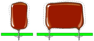
 Dipped version